← Back to Work
CON 570 · Advanced Technology Facilities

LabSPEC Pilot Production Facility — Semiconductor Fab Case Study

Graduate studio project Pilot production ISO 3 / Class 1 Cleanroom High-density MEP

Project Overview

Turning a graduate studio brief into a coordinated semiconductor fab concept.

This case study is based on the LabSPEC Pilot Production Facility developed in CON 570 — Introduction to Advanced Technology Facilities at Arizona State University. The goal was to translate an academic program and slide deck into a buildable fab that can begin as a pilot line and scale toward high-volume manufacturing.

  • Graduate estimating + advanced technology facilities studio.
  • Bay-and-chase cleanroom planning across fab, subfab and plenum.
  • Coordinated MEP logistics for CUB, bulk gas yard and expansion pads.
  • High-density MEP infrastructure sized for ISO 3/4 tools.

Project Role

Pre-construction & planning. I worked on tool layout, zoning of cleanroom vs. support areas, and high-level MEP strategies so the fab could be priced, phased and ultimately built.

Site plan for LabSPEC fab, bulk gas yard, CUB and future expansion areas

Site layout with semiconductor fab, future expansion pad, CUB, electrical yard, bulk gas yard and solar-ready parking.

Cleanroom Stack

Separate levels for people, tools and utilities.

The fab is organized as a three-level stack — plenum, cleanroom and subfab. Ultra-clean process environments are physically separated from heavy mechanical, electrical and chemical infrastructure. This keeps vibration, noise and contamination away from sensitive ISO 3 / 4 process tools.

Bay & Chase Strategy

  • ISO 3/4 process bays separated from maintenance chases.
  • Maintenance access from the “dirty” chase side only.
  • Tools sit on a stiffened structure to control vibration.
  • Long-span framing keeps columns out of critical bays.

Fab Level — ISO 3/4 process bays & gowning

Fab level cleanroom bay and chase layout
Bay-and-chase layout for ISO 3/4 process tools, parts cleaning and gowning / pre-gowning.

Subfab Level — Tool support & chase corridors

Subfab plan showing tool support zones and chemical distribution
Subfab houses tool support zones, gas cabinets, chemical distribution and maintenance corridors directly under the bays above.

Plenum Level — Supply air & return paths

Plenum plan for LabSPEC cleanroom
Plenum level sized to support ISO 3/4 airflow requirements while keeping AHU, ductwork and filters clear of cleanroom operations below.

3D Cutaway — Cleanroom, subfab & plenum stack

3D cutaway view of stacked plenum, cleanroom and subfab levels
3D cutaway of the stacked plenum, cleanroom and subfab structure showing tool support routing and vertical risers between levels.

HVAC Systems

Supporting ISO 3 / Class 1 environments at the heart of the fab.

Objectives

  • Supply airflow in sufficient volume and cleanliness to support the ISO Class 1 cleanroom.
  • Introduce air in a manner that prevents stagnant areas where particles could accumulate.
  • Condition air to maintain cleanroom temperature and humidity requirements.
  • Maintain positive pressure relative to less-clean adjacent areas to prevent particle infiltration.

Cleanroom basis of design. The main cleanroom area is approximately 30,000 SF at ISO 3/4 (Class 1/10) with an additional 5,000 SF ISO 6 (Class 1000) maintenance and parts-cleaning area.

Central chilled water plant layout serving fab and support buildings
Central chilled water plant serving AHUs, process cooling and office loads with N+1 chillers and pumps.

Exhaust Systems

Keeping operators safe while protecting ISO 3 air quality.

Key Objectives

  • Eliminate hazardous gases such as VOCs, NH3, Cl2 and HF.
  • Maintain ISO Class 3 air cleanliness and positive pressure in the cleanroom.
  • Remove heat, fumes and flammable vapors (e.g., silane and hydrogen).
  • Prevent explosion and fire hazards in ducts and plenums.

Airflow Design

  • Cleanroom area: 30,000 SF; target 600 ACH.
  • Total air volume: 480,000 ft³.
  • Exhaust volume: 960,000 CFM (~20% of supply) with make-up air for pressure control.

Key Components

  • Ducts: FRP, stainless steel and PVC as appropriate per NFPA 318 and IMC.
  • Fans: FRP centrifugal for acid/ammonia, explosion-proof for solvent exhaust with N+1 redundancy.
  • Scrubbers: Wet scrubbers for acids & ammonia; dry media for toxic gas & solvents.
  • Filtration: HEPA / ULPA stages on general exhaust as required.
  • Oxidizers: Treat flammable vapors where needed.
  • Sensors: Toxic gas and airflow monitoring integrated to the BMS.

Design and safety criteria reference NFPA 318 & 45, IMC, SEMI and ASHRAE cleanroom guidelines.

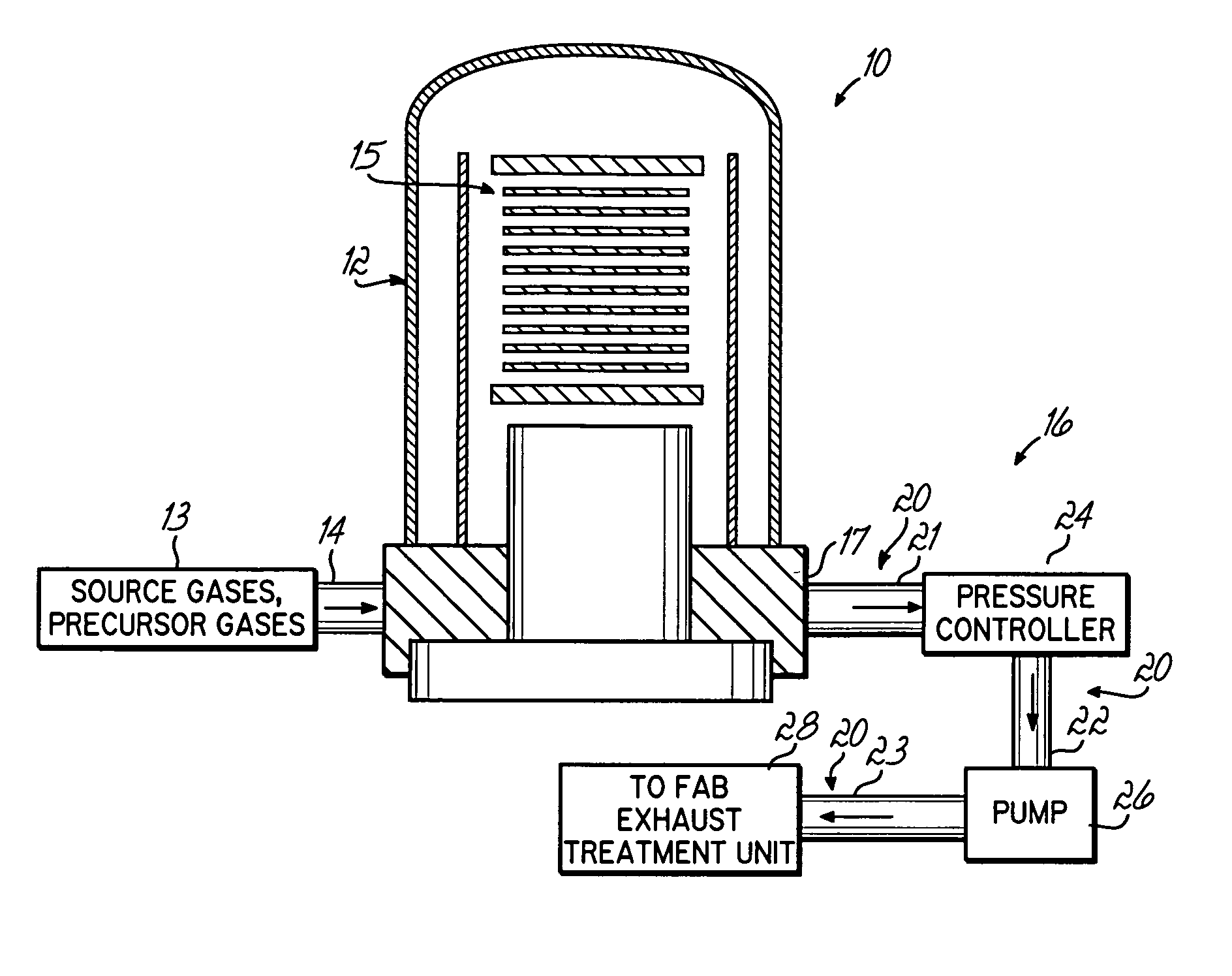
Exhaust and process utility schematics for the LabSPEC fab
Exhaust and process schematics tying together fume hoods, process tools, scrubbers and stack locations.
Vertical scrubber and exhaust stack concept section
Concept section showing a vertical scrubber and exhaust stack — source gases enter, are treated in the chamber, and discharge through a controlled vent.

Ultra-Pure Water & Waste Treatment

Closing the loop on high-purity process water and compliant discharge.

Ultra-Pure Water (UPW) System

The UPW system uses UV oxidation, EDI, reverse osmosis, pre-treatment and ultrafiltration to provide high-resistivity water > 18 MΩ·cm. It maintains extremely low TOC and particle levels for semiconductor fabrication.

Loop distribution, full automation and continuous monitoring ensure constant purity at all tool points across the fab.

Industrial Waste Neutralization

Wastewater streams from fab operations are collected and treated in an industrial neutralization system. Acidic and alkaline flows are blended and actively controlled to maintain a discharge pH of 6.5–8.5.

Real-time pH sensors, a stirred reactor and PLC-controlled acid/base dosing support safe, automated operation. Equalization and holding tanks, interlocks and alarms ensure compliant wastewater handling.

Ultra-pure water system schematic
Ultra-pure water treatment train, from pre-treatment and RO through polishing and distribution loops.
High-level wastewater and reclaim process flow diagram
High-level wastewater and reclaim process flow, tying neutralization, filtration and ZLD strategies together.

Bulk Gas, Specialty Gases & Chemicals

Coordinating the yard, CUB and subfab to keep hazardous materials controlled.

Bulk Gas Yard & CUB Interface

The Bulk Gas Yard is an enclosed, fenced area roughly 75 feet from the main fab. It houses large-volume gas storage feeding the Central Utility Building (CUB) and the subfab gas room.

The Bulk Chemical Dispensing System (BCDS) is located within the CUB adjacent to the fab. A double-contained piping corridor runs approximately 40–50 feet to reach the cleanroom subfab, protecting operators and simplifying spill containment.

Bulk gases Specialty gases BCDS Double-contained piping
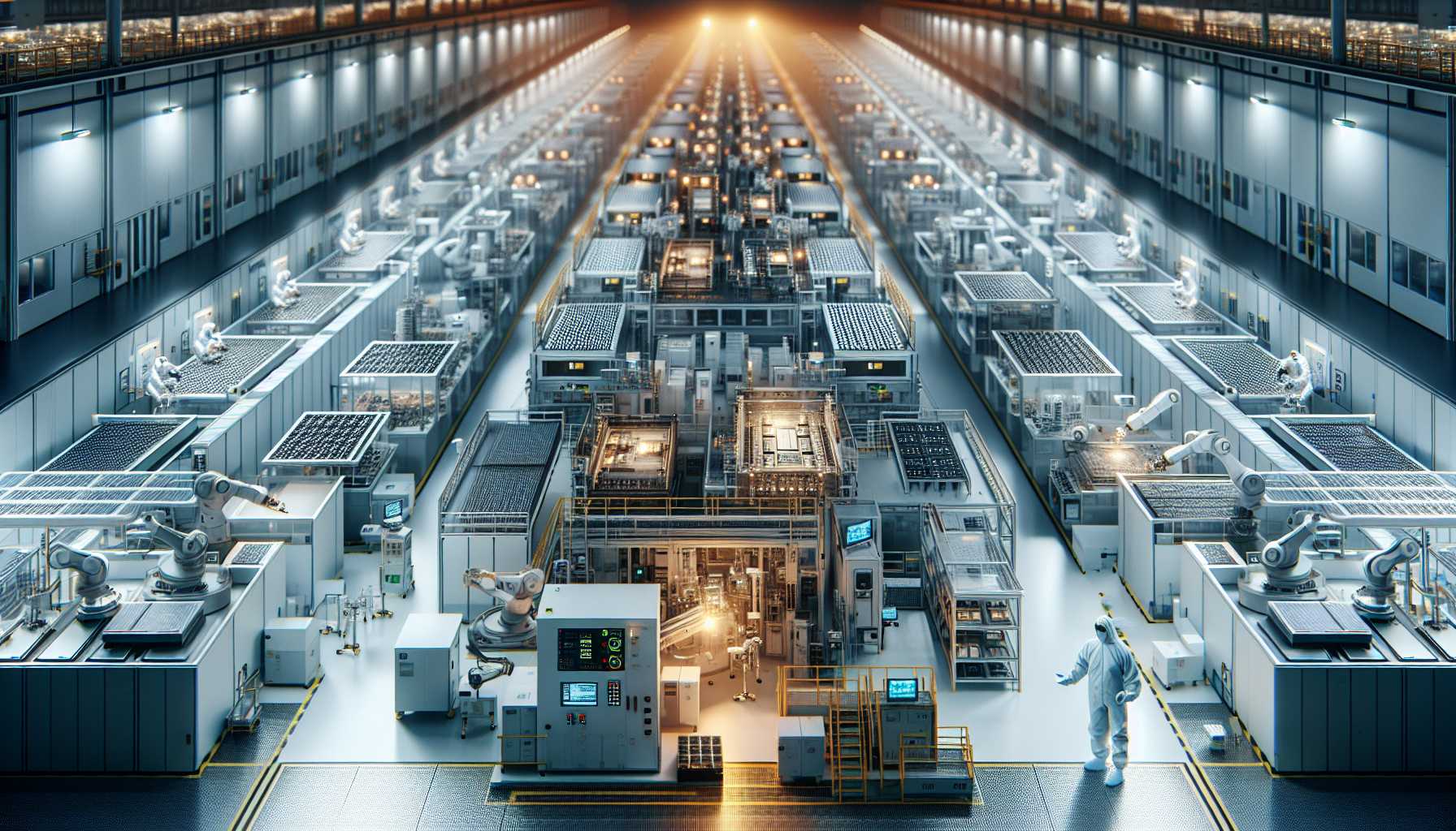
High-tech cleanroom production line interior with tools and automation
Interior perspective of a high-density semiconductor production line, illustrating how tools and utilities fill the cleanroom envelope.
3D massing of bulk gas yard, CUB and subfab gas room

3D massing of the bulk gas yard, CUB and subfab gas room showing separation distances, access and routing of hazardous materials.

Utility gas supply schematic
Utility gas supply schematic showing primary headers and distribution to individual gas cabinets.
Specialty gas distribution to subfab gas room
Specialty gas distribution into the subfab gas room with cabinet exhaust, purge systems and monitoring.
Bulk chemical dispensing system layout
Bulk Chemical Dispensing System (BCDS) layout in the CUB, feeding process tools via double-contained lines.
Additional process flow and utility tie-ins
Additional process flow and utility tie-ins illustrating how gases, chemicals and UPW converge at the tool level.